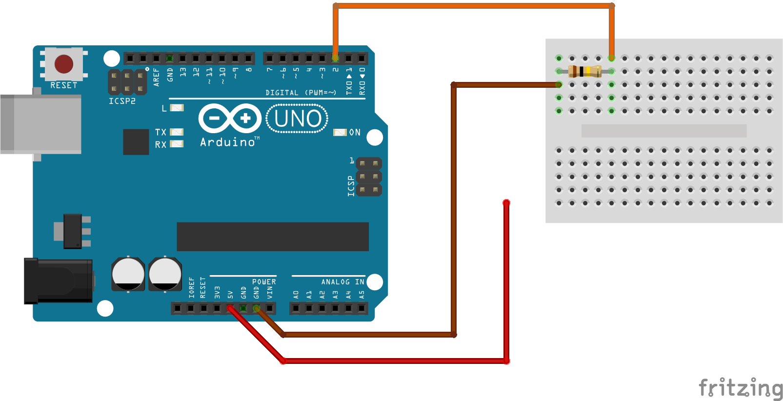
You may well have used some (or all) of the methods above to control your scratch projects in the past. One of the cool things that we can do with an Arduino that we can’t do in Scratch is use the Arduino’s pins as inputs. Here is a diagram showing you how to set up a simple circuit to use digital pin 2 as a switch.

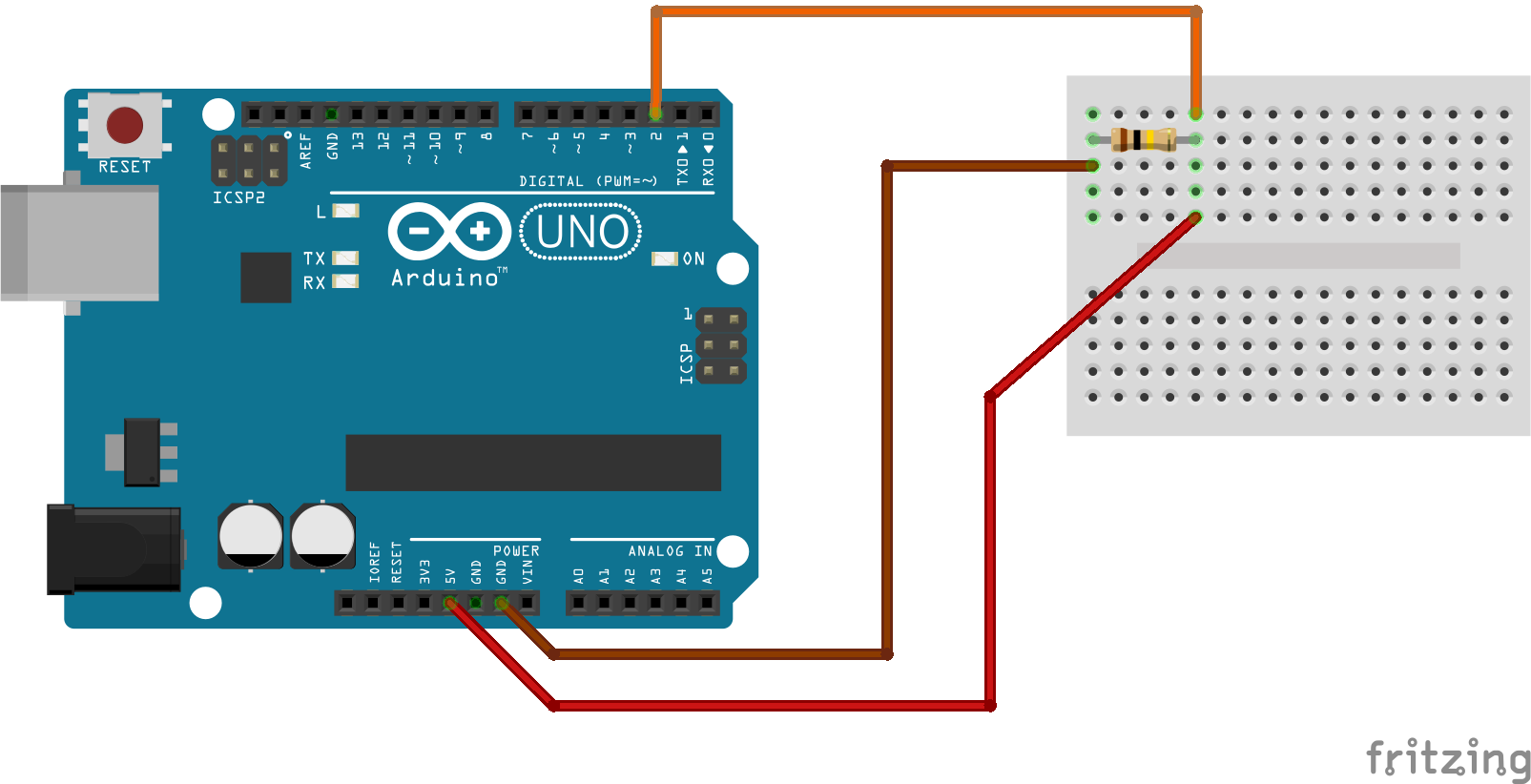
If we want to turn our switch on, we have to connect the wire from 5V as show below. Please check carefully before you do this, as we could damage our LED if we do this the wrong way round! The wire from 5V always needs to be plugged into the same end of the resistor as the wire from pin 2.

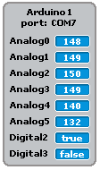
When you close the switch, on your stage (in the top right) you should see the value of Digital2 turn from “false” to “true”

If you see this happening, congratulations! You have just made your first circuit with an Arduino! If this isn’t working like it should then double check your wiring against the diagrams above.

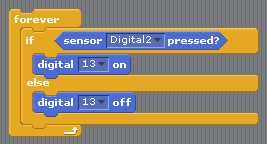
If we want to use this in a script, we will need to use a new block, the “sensor pressed” block. Here’s an example of using the sensor pressed block to control our LED.

With this circuit, you can now use your switch to control all kinds of things in Scratch too! Try getting something to happen in scratch whenever your LED lights up. Maybe even try getting a game or animation in scratch to control your LED too!
